
Concrete foundation wall reinforcing
Codewords 85: July 2018
This article looks at NZS 3604:2011 requirements for reinforcing foundation walls in timber-framed buildings.

NZS 3604:2011 Timber-framed buildings describes reinforcing for in-situ concrete and concrete masonry foundation walls with a piled foundation system supporting lightweight timber-framed construction (refer to paragraph 6.11.7 and Figures 6.13, 6.14 and 6.15 of the Standard).
Basics of reinforcing
Reinforcing generally consists of 12 mm diameter deformed (D12) bars. The use of deformed bars, which have an irregular surface, creates a good bond between the reinforcing and the concrete. They are installed both horizontally and vertically at spacings depending on:
- the height of the wall
- whether the wall is in situ concrete or concrete masonry
- whether the wall is to support 1 or 2-storey construction
- whether the wall is cantilevered or not.
The details for reinforcing in-situ concrete and concrete masonry foundation walls are summarised in Table 1 and shown in Figures 1 and 2.
| Type of Foundation Wall | Reinforcing | |||
|---|---|---|---|---|
| Footing | Wall Horizontal | Wall Vertical | ||
| In situ concrete | 1-storey building (wall not cantilevered) | 1/D12* | D12 @ 450mm centres plus one D12 at top for walls > 1m high | D12 @ 600mm centres for walls >1m high |
| 2-storey building (wall not cantilevered) | 2/D12 | D12 @ 450mm centres plus one D12 at top for walls > 1m high | D12 @ 500mm centres for walls > 1m high | |
| 1 or 2-storey building (cantilevered wall) | D12 @ 400mm centres both ways (see Figure 2) | One D12 @ 400mm centres plus one D12 at top | D12 @ 400 centres maximum | |
| Concrete masonry | 1-storey building (wall not cantilevered) | 1/D12* | One D12 at top and one D12 at mid height for walls > 1m high | D12 @ 800mm centres |
| 2-storey building (wall not cantilevered) | 2/D12 | D12 at mid height for walls > 1m high and D12 at top | D12 @ 800mm centres | |
| Cantilevered wall | D12 @ 400mm centres both ways (see Figure 2) | D12 @ 800mm centres | D12 @ 400mm centres | |
* 2/D12 where foundation wall supports masonary veneer.
Figure 1: Reinforcing for in situ concrete foundation wall for single storey.
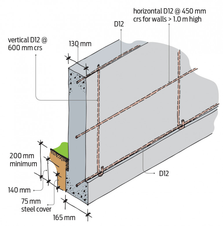
Image supplied by BRANZ Build magazine
Figure 2: Reinforcing for cantilevered foundation wall for 1 or 2 storeys.
Note: Horizontal reinforcing in bond beam @ 800 mm centres.
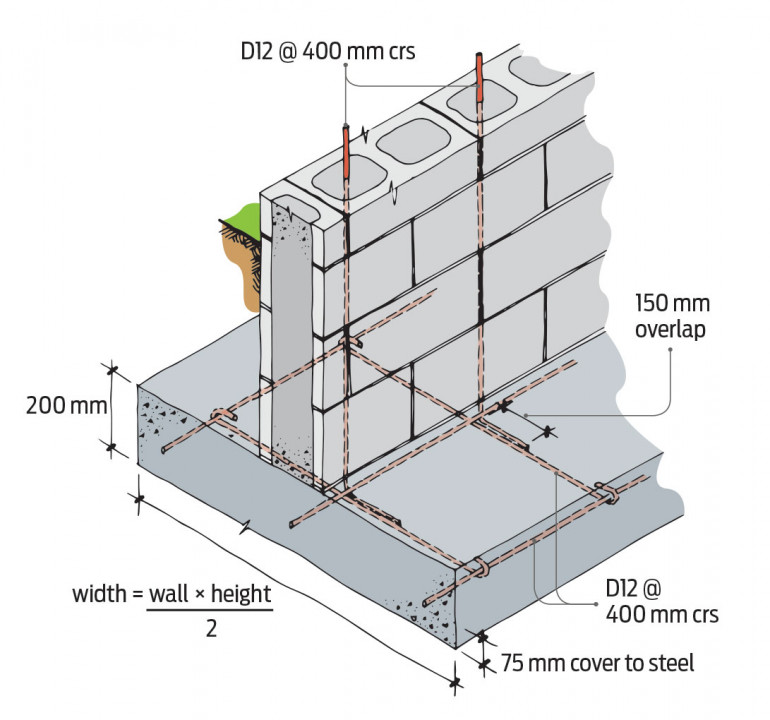
Image supplied by BRANZ Build magazine
When combined with concrete slab-on-ground floors
NZS 3604:2011 contains details of reinforcing for perimeter footings combined with concrete slab-on-ground floors supporting lightweight construction – refer to Figures 7.13(B), 7.14(B) and 7.14(C) of the Standard.
The Standard also contains details of the reinforcing if the combined perimeter footing/concrete slab-on-ground floor also supports masonry veneer cladding – refer to Figures 7.15(B), 7.16(B) and 7.16(C).
The details for reinforcing combined footing/concrete floor slabs are summarised in Table 2 and shown in Figures 3 and 4.
Note that Building Code B1/AS1 Amendment 11 removed the untied slab/footing details in Figures 7.13(A), 7.14(A), 7.15(A) and 7.16(A) of the Standard. All concrete slab-on-ground floors must now be reinforced and the slab reinforcing tied into the perimeter footing reinforcing.
| Foundation Edge Detail | Reinforcing | |||
|---|---|---|---|---|
| Footing (base of foundation wall) | Wall Horizontal (top of foundation wall) | Vertical | Lap (Slab mesh and footing reinforcing) | |
| In-situ concrete (1 or 2 storeys) | Two D12 | One D12 (top) | R10 @ 600 mm centres | 300mm |
| In-situ concrete (1 or 2 storeys supporting masonry veneer) | Two D12 (placed horizontally) | One D12 (top) | R10 @ 600 mm centres | 400mm |
| Concrete masonry (1 or 2 storeys supporting lightweight cladding) | Two D12 (placed horizontally or vertically) | One D12 (top) | R10 @ 600 mm centres (hooked around horizontal reinforcing in footing in alternating directions – see Figure 4) | 300mm |
| Concrete masonry (1 or 2 storeys supporting masonry veneer) | Two D12 (placed horizontally) | One D12 (top) | R10 @ 600 mm centres (hooked around horizontal reinforcing in footing in alternating directions – see Figure 4) | 400mm |
Figure 3: Reinforcing for in situ concrete foundation edge detail for 1 or 2 storeys.
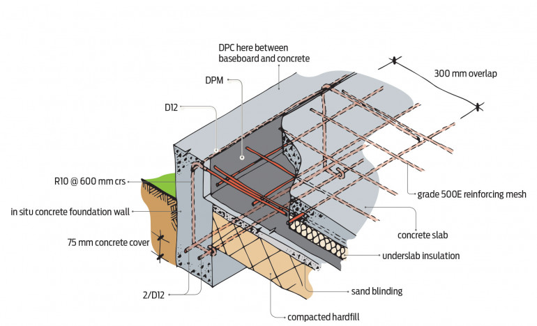
Image supplied by BRANZ Build magazine
Figure 4: Reinforcing for concrete masonry foundation edge detail for 1 or 2 storeys.
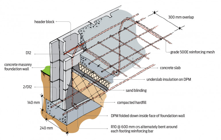
Image supplied by BRANZ Build magazine
Laps and changes in direction
Where horizontal reinforcing bars change direction and in other situations where they must be lapped, the overlaps must be a minimum of 500 mm. At corners, the laps must be at least 500 mm in each direction as shown in NZS 3604:2011 Figure 6.15(a).
Lapped reinforcing should be tied with 1.6 mm black annealed steel wire, which is soft and easily bent, at each end of the lap and at regular spacings in between.
Stirrups and bends
Where pairs of horizontal reinforcing bars are required in the footings of combined foundation wall/concrete slab-on-ground floors, they must be linked by stirrups. The stirrups are formed from the R10 (plain) reinforcing bars installed at 400 mm centres and tied with steel wire ties at the junctions of the reinforcing and the stirrups (see Figure 4). Plain reinforcing bars used as stirrups have a minimum bend diameter of two times the diameter of the bar.
The bends in the deformed longitudinal reinforcing that form a hook or create a right angle must be at least five times the diameter of the bar – for example, the minimum bend diameter for 12 mm diameter deformed reinforcing is 60 mm.
Other reinforcing requirements
Other reinforcing requirements for foundation walls and footings:
Stepped footings must have additional reinforcing in accordance with NZS 3604:2011 Figure 6.12 (see Figure 5).
Figure 5: Stepped foundation walls.
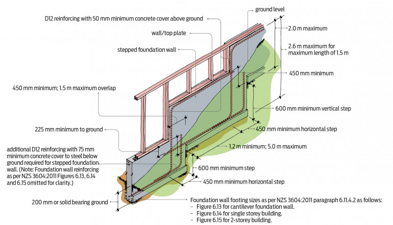
Image supplied by BRANZ Build magazine
Where concrete or concrete masonry is against ground, reinforcing must have a minimum concrete cover of 75 mm.
Openings in foundation walls larger than 300 mm in any direction must have one D12 trimming bar on each side of the opening. These bars must extend at least 600 mm past each corner of the opening. Where a lintel is less than 650 mm deep, the jamb trimming bars must be bent near their tops at 60 mm from the top of the concrete.
Quiz
1. The deformed reinforcing for concrete and concrete masonry foundation walls to NZS 3604:2011 is:
- 8mm in diameter
- 10mm in diameter
- 12mm in diameter
- 16mm in diameter.
2. Deformed bars are used because they:
- slip more easily through the concrete
- form a good bond with the concrete.
3. Laps to the D12 horizontal reinforcing must be at least:
- 300mm
- 500mm
- 700mm
- 1000mm
4. The minimum bend diameter of R10 reinforcing for stirrups is:
- 20mm
- 55mm
- 60mm
- 65mm
Check answers
1. The deformed reinforcing for concrete and concrete masonry foundation walls to NZS 3604:2011 is:
c. 12mm in diameter
2. Deformed bars are used because they:
b. form a good bond with the concrete
3. Laps to the D12 horizontal reinforcing must be at least:
b. 500mm
4. The minimum bend diameter of R10 reinforcing for stirrups is:
a. 20mm